Tony's
Welding Pictures
The TIG Clamping Jig
The TIG Clamping Jig
(click
on the small pictures to see a larger picture in a new browser window)
-
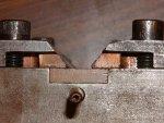
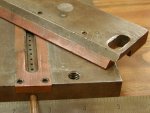
End view of the jig showing the gas tube and how the clamps mate to the surface of the jig. -
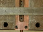
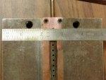
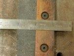
Width of the copper insert is 1 inch. -
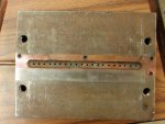
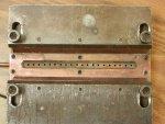
Entire top surface of the jig. -
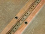
In this view of the steel jig you can see the copper and also see the gas vent holes in the slot. -
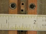
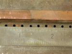
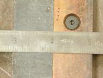
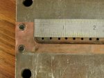
The vent holes and spacing. The groove that they are in is about 1/8 inch deep with the bevel going down 1/16 inch. -
Measurements across the end of the jig. -
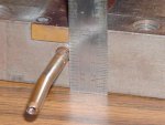
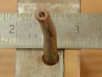
Gas feed tube. -
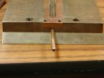
End of the jig showing the gas tube and copper insert. -
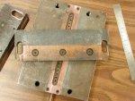
The top clamp laying on the surface. -
The back side of one of the top clamps. -
The top clamp back side close up. -
The pieces . -
The top clamp laying on the surface. -
The top clamp laying on the surface. -
Top view of the jig. -
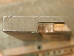
The end of one top clamp. -
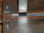
Depth of the groove. -
Hole spacing .
